
 by
by How to Configure QinQ on Huawei Switch port/interface:
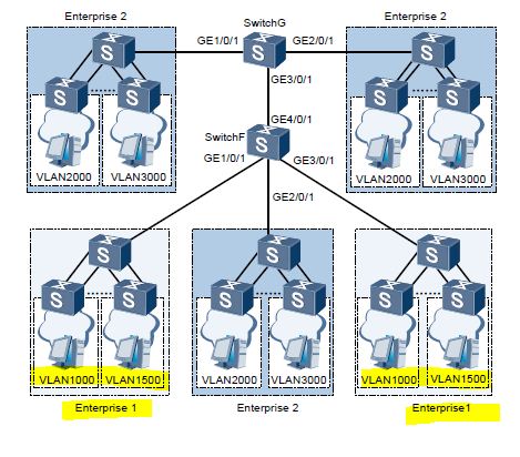
Today I will show how to configure QinQ in Huawei Switch port/interface. As shown in Figure, there are two enterprises on the network, namely, Enterprise 1 and Enterprise 2. Enterprise 1 has two office locations; Enterprise 2 has three office locations. The office locations of the two enterprises access SwitchG or SwitchF of the ISP network.
[boxads]
The network of Enterprise 1 is divided into VLAN 1000 to VLAN 1500; the network of Enterprise 2 is divided into VLAN 2000 to VLAN 3000. It is required that employees in the same VLAN can communicate with each other through the ISP network but the two enterprises are isolated from each other.
Configuration Roadmap:
The configuration roadmap is as follows:
1. Create VLAN 10 and VLAN 20 on SwitchF; create VLAN 20 on SwitchG.
2. Configure GE 1/0/1, GE 2/0/1, and GE 3/0/1 of SwitchF as QinQ interfaces.
3. Configure GE 1/0/1 and GE 2/0/1 of SwitchG as QinQ interfaces.
4. Add GE 4/0/1 of SwitchF and GE 3/0/1 of SwitchG to VLAN 20 in tagged mode.
[adsense]
Data Preparation:
To complete the configuration, you need the following data:
- VLAN 10 assigned to Enterprise 1 on the ISP network
- VLAN 20 assigned to Enterprise 2 on the ISP network.
Procedure:
Step-1: Create VLANs.
# Create VLAN 10 and VLAN 20 on SwitchF.
<Quidway> system-view
[Quidway] sysname SwitchF
[SwitchF] vlan batch 10 20
# Create VLAN 20 on SwitchG.
<Quidway> system-view
[Quidway] sysname SwitchG
[SwitchG] vlan 20
Step-2: Configure the interfaces as QinQ interfaces.
# Configure GE 1/0/1, GE 2/0/1, and GE 3/0/1 of SwitchF as QinQ interfaces. Set the VLAN ID of the outer VLAN tag added by GE 1/0/1 and GE 3/0/1/ to VLAN 10; set the VLAN ID of the outer VLAN tag added by GE 2/0/1 to VLAN 20.
[SwitchF] interface gigabitethernet 1/0/1
[SwitchF-GigabitEthernet1/0/1] port link-type dot1q-tunnel
[SwitchF-GigabitEthernet1/0/1] port default vlan 10
[SwitchF-GigabitEthernet1/0/1] quit
[SwitchF] interface gigabitethernet 2/0/1
[SwitchF-GigabitEthernet2/0/1] port link-type dot1q-tunnel
[SwitchF-GigabitEthernet2/0/1] port default vlan 20
[SwitchF-GigabitEthernet2/0/1] quit
[SwitchF] interface gigabitethernet 3/0/1
[SwitchF-GigabitEthernet3/0/1] port link-type dot1q-tunnel
[SwitchF-GigabitEthernet3/0/1] port default vlan 10
[SwitchF-GigabitEthernet3/0/1] quit
# Set GE 1/0/1 and GE 2/0/1 of SwitchG as QinQ interfaces; set the VLAN ID of the outer VLAN tags added by GE 1/0/1 and GE 2/0/1/ to VLAN 20.
[SwitchG] interface gigabitethernet 1/0/1
[SwitchG-GigabitEthernet1/0/1] port link-type dot1q-tunnel
[SwitchG-GigabitEthernet1/0/1] port default vlan 20
[SwitchG-GigabitEthernet1/0/1] quit
[SwitchG] interface gigabitethernet 2/0/1
[SwitchG-GigabitEthernet2/0/1] port link-type dot1q-tunnel
[SwitchG-GigabitEthernet2/0/1] port default vlan 20
[SwitchG-GigabitEthernet2/0/1] quit
[bodyads]
Step-3: Configure other interfaces.
# Add GE 4/0/1 of SwitchF to VLAN 20.
[SwitchF] interface gigabitethernet 4/0/1
[SwitchF-GigabitEthernet4/0/1] port link-type trunk
[SwitchF-GigabitEthernet4/0/1] port trunk allow-pass vlan 20
[SwitchF-GigabitEthernet4/0/1] quit
# Add GE 3/0/1 of SwitchG to VLAN 20.
[SwitchG] interface gigabitethernet 3/0/1
[SwitchG-GigabitEthernet3/0/1] port link-type trunk
[SwitchG-GigabitEthernet3/0/1] port trunk allow-pass vlan 20
[SwitchG-GigabitEthernet3/0/1] quit
Step-4: Verify the configuration.
Ping a remote host on the same VLAN in another office location of Enterprise 1 from a host of Enterprise 1. If it can ping the remote host, hosts in different locations of Enterprise 1 can communicate with each other.
Ping a remote host on the same VLAN in another office location of Enterprise 2 from a host of Enterprise 2. If it can ping the remote host, hosts in different locations of Enterprise 2 can communicate with each other.
Ping a host of Enterprise 2 from a host in any office location of Enterprise 1. If it fails to ping the host of Enterprise 2, the two enterprises are isolated from each other.
Configuration Files:
The following lists the configuration files of the Switch.
Configuration file of SwitchF
#
sysname SwitchF
#
vlan batch 10 20
#
interface GigabitEthernet1/0/1
port link-type dot1q-tunnel
port default vlan 10
#
interface GigabitEthernet2/0/1
port link-type dot1q-tunnel
port default vlan 20
#
interface GigabitEthernet3/0/1
port link-type dot1q-tunnel
port default vlan 10
#
interface GigabitEthernet4/0/1
port link-type trunk
port trunk allow-pass vlan 20
#
return
Configuration file of SwitchG
#
sysname SwitchG
#
vlan batch 20
#
interface GigabitEthernet1/0/1
port link-type dot1q-tunnel
port default vlan 20
#
interface GigabitEthernet2/0/1
port link-type dot1q-tunnel
port default vlan 20
#
interface GigabitEthernet3/0/1
port link-type trunk
port trunk allow-pass vlan 20
#
return