Layer 2 Switching process
Today I will discuss about Layer 2 Switching process. A Process of using the MAC address on LAN is called Layer 2 Switching.
Layer 2 Switching is the process of using hardware address of devices on a LAN to segment a network. Switching breaks up large collision domains into smaller ones and that a collision domain is a network segment with two or more devices sharing the same bandwidth. [boxads]
Ethernet is a LAN technology based on the IEEE 802.3 standard. It provides a shared medium to transfer the data.
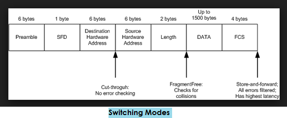
There are three Switching Modes:
- Cut through (Fast Forward)- When in this mode, the switch only waits for the destination hardware address to be received before it looks up the destination address in the MAC filter table. Cisco sometimes calls this the fast forward method.
- Fragment Free (Modified cut through)- This is the default mode for the catalyst 1900 switch, and it’s sometimes referred to as modified cut through. In fragment free mode, the switch checks the first 64 bytes of a frame before forwarding it for fragmentation, thus guarding against forwarding runts, which are caused by collisions.
- Store and forward- In this mode the complete data frame is received on the switch’s buffer, a CRC is run, and if the CRC passes, the switch looks up the destination address in the MAC filter table.
Functions of a Switch:
- Address Learning– A switch learns MAC address based on Source MAC.
- Forward Filter Decision– A switch forwards a frame based on destination MAC.
- Loop Avoidance– Switch use STP to prevent a network from looping.
We always use Store and forward switch.
Flooding – A process of transferring a frames copy to its all ports except that port on which it was received.
Switch floods three types of frame
- Broadcast (FF: FF: FF: FF: FF: FF or 255.255.255.255)
- Multicast (start from 0100)
- Unknown Unicast
Switches are two types
(i) Modular 2950, 3550 (Fixed)
(ii) De-Modular 4500, 6500 (We can modify)
(Note: 2960, 3560 – It supports stacking.)
Routing Rules:
- If the destination is in the same subnet or network then a device directly sends the packet to the destination.
- If destination is not in same subnet or network then a device directly send packet to default gateway.
(Note: ARP Request is used to find out the Destination MAC. Cisco 6500 series switch can store 1.80 lac MAC Address.)
[bodyads]
Types of Switching:
- Layer 2 Switching
Layer 2 switches learn MAC addresses automatically, building a table which can be used to selectively forward packets. For example, if a switch receives packets from MAC address X on Port 1 it then knows that packets destined for MAC address X can simply be forwarded out of that port rather than having to try each available port in turn.
- Layer 3 Switching
- In layer 3 switching packets are forwarded based on destination L3 information as a router does.
- Packets are forwarded with high speed as compared to router.
- Packets are switched using dedicated hardware.
- Layer 4 Switching
In layer 4 switching TCP & UDP port numbers are checked.
- MLS
In Multi-layer switching Data is forwarded based on L2, L3 & L4 information.
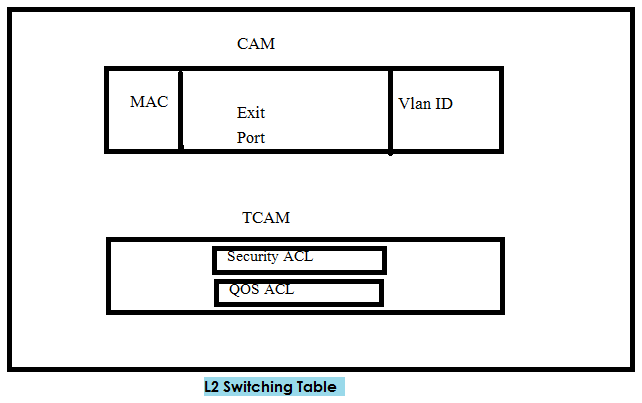
CAM- Content Addressable Memory
TCAM- Ternary Content Addressable Memory
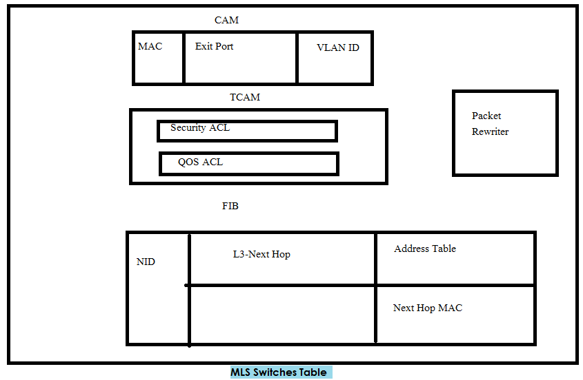
FIB – Forwarding information Base
As a router maintain routing table just like this a MLS maintains FIB.
Packet Rewriter-
- Write Source-Destination MAC
- Decrease TTL Value
TCAM Components
SDM is used for Storage
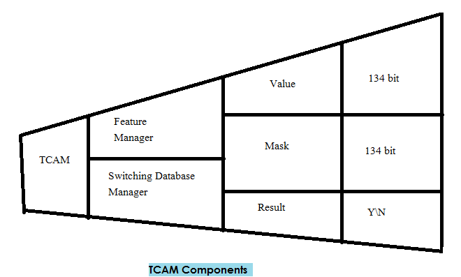
FM – to compile ACL
- Ingress Que – Incoming data
- Egress Que – Outgoing data
VLAN
Before understand VLAN we have to understand LAN.
A LAN consists of all devices in a single broadcast domain.
Broadcast Domain- A set of LAN connected devices in which when a device sends a broadcast then all devices get a copy of frame so LAN & Broadcast domain are same thing.
By default a switch consider its all interface in a single broadcast domain but a switch has ability to put some interface in one broadcast domain & some interfaces in another broadcast domain. These new broadcast domain are called V-LAN.
Types of VLAN
- Static Vlan- Static Vlan provides port based Vlan membership. In static Vlan we configure switch ports in a particular Vlan.
When we manually add switch ports to specific vlans.
Switch (config) #vlan 10
Switch (config-vlan) #name Hr
Switch (config) #int fa0/1
Switch (config-if) #switchport mode access
Switch (config-if) #switchport access vlan 10
- Dynamic Vlan- Dynamic Vlan provides Vlan membership based on MAC. When any end device is connected with the switch, then switch learn the MAC address of end devices. After learning MAC it sends a request to VMPS (Vlan Management Policy Server) that I have a MAC, now tell me VLAN ID of this MAC. Now VMPS is responsible for Vlan assignment based on MAC. Now a day we use AAA (Authentication, Authorization & accounting) for dynamic vlans. It works based on username and password of a user.
VLAN Trunking
When a switch sends a frame to another switch then it adds an extra header with the frame which contains VLAN ID of frame. This process is called VLAN trunking or tagging.
Types of Trunking Protocol
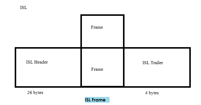
ISL (Inter Switch Link)- it is a cisco proprietary protocol. It encapsulate original Ethernet frame with ISL header & trailer. It inserts 26 bytes header & 4 bytes trailer. This process is also called dual tagging. It doesn’t support untagged data and native vlan.
802.1Q– It is an open standard protocol. It doesn’t encapsulate original Ethernet frame with dot1Q header & trailer but it insert 4 byte dot1Q header in original Ethernet header. It supports untagged data and native vlans.
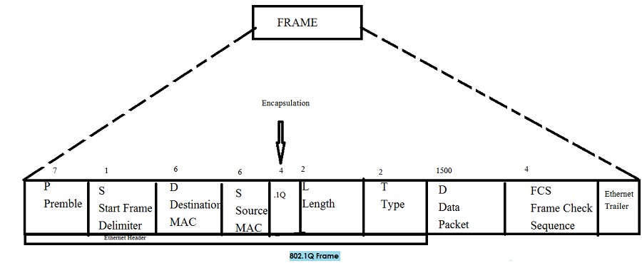
Dot1q 4 bytes divided into two parts
(i)TPI – Tag Protocol Identifier
(ii)TCI – Tag Control Information
TCI – 3 bits cos – class of service
4th bit- CFI Canonical format (for topology)
12 bit – vlan id
DTP (Dynamic Trunking Protocol)- Cisco proprietary protocol.
DTP Modes- (i) DD (ii) DA (iii) nonegotiate
3550 – By default mode is DD
3560 – By default mode DA
To disable DTP on cisco switches
Switch (config) #int fa0/1
Switch (config-if) #switchport nonegotiate
Before run this command we need to make this interface at least part of access list or trunk link. Only we will be able to run this command.
By default DTP is enabled on switches
Allowed vlan via trunk 1 to 4094
Switch#sh int trunk
Switch#sh int status
Vlan range – 0 to 4095
Valid range – 1- 4094
Normal Range of Vlan
1 to 1005
Default created Vlans in Normal range
1 Native vlan
1002 fddi-default
1003 token-ring-default
1004 fddinet-default
1005 trnet-default
Extended Range:
1006 to 4094
Reserved:
4095
(Note- Extended range vlan we can only create in Transparent mode.)
VTP Version 3 supports Extended Range.
[adsense]
Vlan trunk configuration
Switch (config) #int fa0/0
Switch (config-if) #switchport trunk encapsulation (ISL, dot1q, negotiate)
Switch (config-if) #switchport trunk native vlan (vlan –id)
Switch (config-if) #switchport trunk allowed vlan (vlan-list, all)
Switch (config-if) #switchport mode (trunk, dynamic, auto)
DD —————————————————————-DD Yes
DA—————————————————————–DA No
DA—————————————————————–DD Yes
Static————————————————————-DD Yes
DA—————————————————————-Static Yes
Static————————————————————-Static Yes
- Trunk– This setting place the port in permanent trunking mode. DTP is still operational so if the far-end switch port is configured to trunk, DD, or DA, trunking will be negotiated successfully.
- DD – (Dynamic Desirable) the port actively attempts to convert the link into trunking mode. In other words, it asks the far-end switch to bring up a frame. If the far-end switch port is configured to trunk, DD or DA mode, trunking is negotiated successfully.
- DA – (Dynamic Auto) the port can be converted in to a trunk link, but only if the far-end switch actively request it. Therefore, if the far-end switch port is configured to trunk or DD mode, trunking is negotiated. Because of passive negotiation behavior, the link never becomes a trunk if both ends of the link are left to the Dynamic auto.
In all these modes, DTP frames are sent out every 30 sec to keep neighboring switch ports informed of the links mode.
Switch (config) #int gig 2/1
Switch (config-if) #switchport trunk encapsulation dot1q
Switch (config-if) #switchport trunk native vlan 100
Switch (config-if) #switchport trunk allowed vlan 100 – 105
Switch (config-if) #switchport mode DD
Switch#sh int gig 2/1 trunk
Switch#sh int status
Switch (config) #int gig 2/1
Switch (config-if) #switchport trunk allowed vlan remove 103
Switch#sh vlan id
Switch#sh int fa0/2 switchport
Switch#sh dtp (int type)
FDDI – fiber distribution data interface.
CEF – Cisco express forwarding
By default idle CAM table entries are kept for 300 seconds before they are deleted. We can change the default setting using the following command.
Switch (config) #mac address-table aging-time (seconds)
By default, MAC addresses are learned dynamically from incoming frames. We can also configure static CAM table entries that contain MAC addresses that might not be learned otherwise. To do this use following commands
Switch (config) #mac-address-table static (mac-address) vlan (vlan-id) interface type (mod|num)
To view the contents of the CAM table, we can use the following form of the command
Switch #sh mac address-table dynamic
Checking the size of the CAM-Table count
Switch#sh mac address-table count
CAM table entries can be cleared manually
Switch#clear mac address-table dynamic
To select a single switch port
Switch #int fastEthernet 0/14
Select all 48 FastEthernet interfaces on Module 1
Switch (config) #int range fastEthernet 1 0/1 – 48
To set the link mode on a switch port, enter the following command
Switch (config-if) #duplex (auto|full|half)
Switch (config-if) #speed auto
Detecting error Conditions
By default, a catalyst switch detects an error condition on every switch port for every possible cause. If an error condition is detected the switch port is put in to the errdisable state and disabled.
Switch (config) # (no) errdisable detect cause (all|cause name)
We can repeat this command to enable or disable more than one cause.
By default ports put into the errdisable state must be re enabled manually. This is done by issuing the shut down and then no shut.
Switch (config) # errdisable recovery cause (all |cause name)
Switch (config) #errdisable recovery interval

