
 by
by Spanning Tree Protocol Overview
Today I will discuss about Spanning Tree Protocol. STP prevents a network from frame looping by putting some interfaces in forwarding state & some interfaces in blocking state. [boxads]
If we don’t use STP, these problems will occur on the network:
1. Elect Root Bridge
2. Elect Designated Port
3. Elect Root Port
Root Bridge- A switch which has best bridge ID (Lower Best)
Bridge ID is a combination of Switch priority and its MAC addresses. It is 8 bytes ID. It contains 2 bytes priority Plus 6 bytes MAC.
Switches by default Priority is 32768.
We can change the priority between 0-65535.
MAC- Each Switch has a supervisor engine. Supervisor engine has a MAC pool, the pool contain 1024 MAC addresses. When a switch wants to create Bridge ID, it borrows MAC from MAC Pool. [bodyads]
Requirements for Root Bridge
1. Lower Bridge Priority
2. Lower Mac Address.
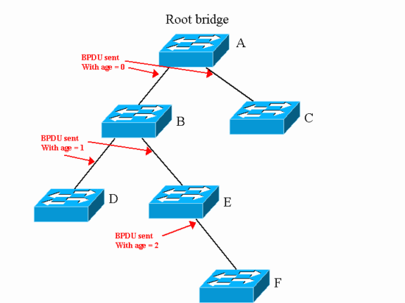
(Note: Rood Bridge Always Generates 0 Cost BPDU.)
Requirements for DP and RP
1. Lower Bridge ID (Only for DP, Between Root & Non Root)
2. Lower Cost | For DP & RP
3. Lower Sender Bridge ID | B/W Root – Non Root
4. Lower Sender Port Priority | Non Root – Non Root
5. Lower Sender Port ID
(Note: All Ports of Root Bridge are DP. Every non root bridge must have at least one root port.)
BPDU: BPDU (Bridge Protocol Data Unit) is a multicast frame that is used to share information about switch and its interface connections. Switches use BPDU to learn the network topology; other switches connections and any existing loops. BPDU frames are sent out as multicast in every two seconds.
Root Bridge: All decisions in Spanning Tree Protocol are made from the perspective of root bridge. Switch with the lowest switch ID is selected as root bridge. BPDU contains Switch ID. Switch ID is made from priority of the switch and MAC address of switch itself. Default priority is set to 32768. Switch with lowest MAC address will be selected as the root switch, if you don’t change the default priority value. You can override root selection process by changing the priority value. If you want one switch to be root bridge, change its priority value to less than 32768.
Selection process of root bridge runs each time a network change occurs like as adding new switch in topology, removing existing switch or root bridge failure. If other switches in network do not receive BPDUs from root bridge within 20 seconds, they assume that root bridge has failed and will begin a new election process to choose a new root bridge.
Non-Root Bridge: All other switches in network except root bridge are the non-root bridges. Non-root Bridge receives update from root bridge and update its STP database.
Port Costs: STP assigns each port a cost, called port cost. Port cost is used to choose best path when multiple links are available between two switches. Cost of port is determined by the bandwidth of connected media link. Switch always use lower port cost to forward the frames. Two set of port costs exist.
| Bandwidth | Old Cost Value | New Cost Value |
| 10 Gbps | 1 | 2 |
| 1 Gbps | 1 | 4 |
| 100 Mbps | 10 | 19 |
| 10 Mbps | 100 | 100 |
Some old series switches like Catalyst 1900 uses old cost value. Cisco already discontinued these old series switches. New series switches like 2960 uses new cost value. Lower cost value is always preferred over higher cost value while selecting link.
Path Costs: Path cost is an accumulated value of port costs from root bridge to other switches in network. It is always calculated from root bridge. Default path cost at root bridge is 0. BPDU contains path cost information. When root bridge advertises BPDU out from its interface, it set path costs to 0. When connected switch receives this BPDU, it increments path cost by adding the port cost value of its incoming port. For example if switch receive this BPDU on Gigabit interface then path cost would be 0 (Value it receive from root bridge) + 4 (port cost value, see above table) equal to 4. Now this switch will set path cost value 4 in BPDU frame and forward it. Assume that next switch is connected with this switch and receive updated BPDU on fast Ethernet port. Path cost for new switch would be 23. Path costs value received in BPDU + Port cost ( 4+ 19 = 23).
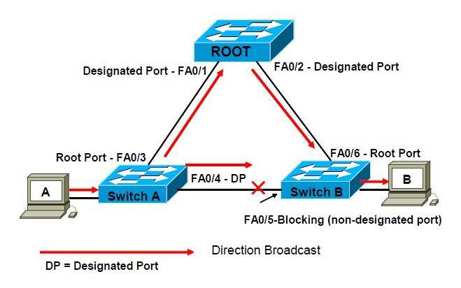
Root Port: Root port is a port that is directly connected with the root bridge, or has the shortest path to the root bridge. Shortest path is path that has lowest path cost value. Remember that switch can go through many other switches to get the root. So it’s not always the shortest path but it is the fastest path that will be used.
Designated Port: Designated port is the port that is selected as having the lowest port cost. Designated port would be marked as forwarding port.
Non-Designated Port: Non-designated port is the port that is selected as having the higher port cost than the designated port. Non-designated port would be marked as blocking port.
Forwarding Port: Forwarding port is used to forward the frames.
Blocking Port: Blocking port remains disable to remove loops.
Spanning Tree Protocol (STP) port states
Ports on switch running STP go through the five different states. During Spanning Tree Protocol convergence, switches will move their root and designated ports through the various states: blocking, listening, learning, and forwarding, whereas any other ports will remain in a blocked state.
Blocking: In blocking state, switch only listen and process BPDUs on its ports. Any other frames except BPDUs are dropped. In this state, switch try to find out which port would be root port, which ports would be designated ports and which ports would be remains in blocking state to remove loops. A port will remain in this state for twenty seconds. By default all ports are in blocking state, when we powered on the switch. Only root port and designated ports will move into next state. All remaining ports will remain in this state.
Listening: After twenty seconds, root port and designated ports will move into listening state. In this state ports still listen and process only BPDUs. All other frames except BPDUs are dropped. In this state switch will double check the layer 2 topology to make sure that no loops occur on the network before processing data frames. Ports remain in this state for fifteen seconds.
Learning: Root port and designated ports enter in learning state from listening state. In this state ports still listen and process BPDUs. However, in this state ports start processing user frames. Switch examines source address in the frames and updates its MAC Address Table. Switch will not forward user frames to destination ports in this state. Ports stay in this state for fifteen seconds.
Forwarding: In forwarding state, ports will listen and process BPDUs. In this state ports will also process user frames, update MAC Address Table and forward user traffic through the ports.
Disable: Disable ports are manually shut down or removed from STP by an administrator. All unplugged ports also remain in disable state. Disable ports do not participate in STP.
Convergence: Convergence is a state where all ports on switch have transitioned to either forwarding or blocking modes. During the STP converging, all user data frames would be dropped. No user data frame will be forwarded until convergence is complete. Usually convergence takes place in fifty seconds (20 seconds of blocking state + 15 seconds of listing state + 15 seconds of learning state).
[bodyads]
Types of Spanning Tree Protocol (STP):
Like many networking standards, there are many types or variants of Spanning Tree Protocol. These include:
- PVST+
- RSTP
- Rapid-PVST+
- MSTP
You will learn more details on some of these Spanning Tree Protocol variants, but to get started you need to have a general knowledge of what the key STP variants are. Below, is a brief description of the key Cisco and IEEE STP variants.
Cisco Proprietary:
IEEE Standards:
Rapid Spanning Tree Protocol (RSTP) – First introduced in 1982 as an evolution of STP (802.1D standard). It provides faster spanning-tree convergence after a topology change. RSTP implements the Cisco-proprietary STP extensions, BackboneFast, UplinkFast, and PortFast, into the public standard. As of 2004, the IEEE has incorporated RSTP into 802.1D, identifying the specification as IEEE 802.1D-2004. So when you hear STP, think RSTP.