Configure Port Channel CISCO Switch:
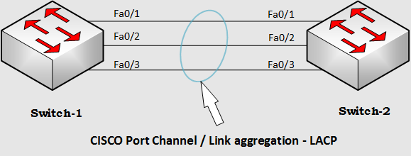
EtherChannel bundles individual Ethernet links into a single logical link that provides bandwidth up to 1600 Mbps (Fast EtherChannel, full duplex) or 16 Gbps (Gigabit EtherChannel) between two Cisco Catalyst switches. All interfaces in each EtherChannel must be the same speed and duplex, and both ends of the channel must be configured as either a Layer 2 or Layer 3 interface. [boxads]
If one link within the EtherChannel bundle fails, traffic previously carried over the failed link is carried over the remaining links within the EtherChannel.
Link Aggregation protocols are:
- IEEE standard Link Aggregation Protocol (LACP)
- Cisco’s proprietary Port Aggregation Protocol (PAgP).
PAgP packets are sent between Fast EtherChannel-capable ports to negotiate the forming of a channel. When PAgP identifies matched Ethernet links, it groups the links into an EtherChannel. The EtherChannel is then added to the spanning tree as a single bridge port.
| Mode (PAgP) | Description |
| Auto | Places an interface into a passive negotiating state, in which the interface responds to PAgP packets it receives but does not start PAgP packet negotiation. This setting minimizes the transmission of PAgP packets and is the default. |
| Desirable | Places an interface into an active negotiating state, in which the interface starts negotiations with other interfaces by sending PAgP packets. |
| On | Forces the interface to channel without PAgP. With the on mode, a usable EtherChannel exists only when an interface group in the on mode is connected to another interface group in the on mode. |
LACP is part of an IEEE specification (802.3ad) that allows several physical ports to be bundled together to form a single logical channel. LACP allows a switch to negotiate an automatic bundle by sending LACP packets to the peer. It performs a similar function as PAgP with Cisco EtherChannel. Because LACP is an IEEE standard, it can be used to facilitate EtherChannels in mixed-switch environments.
| Mode (LACP) | Description |
| Passive | The switch does not initiate the channel, but does understand incoming LACP packets. The peer (in active state) initiates negotiation (by sending out an LACP packet) which we receive and reply to, eventually forming the aggregation channel with the peer. This is similar to the auto mode in PAgP. |
| Active | We are willing to form an aggregate link, and initiate the negotiation. The link aggregate will be formed if the other end is running in LACP active or passive mode. This is similar to the desirable mode of PAgP. |
| On | The link aggregation is forced to be formed without any LACP negotiation .In other words, the switch will neither send the LACP packet nor process any incoming LACP packet. This is similar to the on state for PAgP. |
Etherchannel Negotiation Protocols:
| Negotiation Mode | Packets Sent? | Charateristics | |
| PAgP | LACP | ||
| on | on | No | All ports channeling |
| auto | passive | Yes | Waits to channel until asked |
| desirable | active | Yes | Actively asks to form a channel |
[adsense]
Matrix of Load Balancing Methods:
Cisco EtherChannel technology is composed of several Fast Ethernet links and is capable of load balancing traffic across those links. Unicast, broadcast, and multicast traffic is evenly distributed across the links, providing higher performance and redundant parallel paths. When a link fails, traffic is redirected to the remaining links within the channel without user intervention and with minimal packet loss. To define the load-balance method, enter in the global configuration mode and use the command “port-channel load-balance ?” to see the load-distribution method available.
This matrix consolidates the load balancing methods:
| Platform | Address Used in XOR | Source-Based? | Destination-Based? | Source-Destination-Based? | Load Balancing Method—Configurable/Fixed? |
| 6500/6000 | Layer 2, Layer 3 addresses, Layer 4 information, or MPLS information ² | Yes | Yes | Yes | Configurable |
| 5500/5000 | Layer 2 address only | — | — | Yes | Cannot change the method |
| 4500/4000 | Layer 2, Layer 3 addresses, or Layer 4 information | Yes | Yes | Yes | Configurable |
| 2900XL/3500XL | Layer 2 address only | Yes | Yes | — | Configurable |
| 3750/3560 | Layer 2 or Layer 3 address only | Yes | Yes | Yes | Configurable |
| 2950/2955/3550 | Layer 2 address only ¹ | Yes | Yes | —1 | Configurable |
| 1900/2820 | These platforms use a special method of load balancing. See the Catalyst 1900/2820 section for details. | ||||
| 8500 | Layer 3 address only | — | — | Yes | Cannot change the method |
- For the 3550 series switch, when source-MAC address forwarding is used, load distribution based on the source and destination IP address is also enabled for routed IP traffic. All routed IP traffic chooses a port based on the source and destination IP address.
- For the 6500 series switches that run Cisco IOS, MPLS layer 2 information can also be used for load balancing MPLS packets.

Layer2 Etherchannel Configuration:
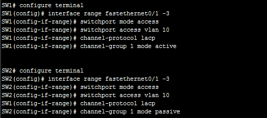
In this example, the FastEthernet 0/1-0/2-0/3 (on SW1 and SW2) must belong to vlan 10; it is required to create a Layer2 etherchannel using LACP with desirable mode on SW1 and passive mode on the SW2. The configuration is:
Switch-1 Configuration:
SW1# configure terminal
SW1(config)# interface range fastethernet0/1 -3
SW1(config-if-range)# switchport mode access
SW1(config-if-range)# switchport access vlan 10
SW1(config-if-range)# channel-protocol lacp
SW1(config-if-range)# channel-group 1 mode active
[bodyads]
Switch-2 Configuration:
SW2# configure terminal
SW2(config)# interface range fastethernet0/1 -3
SW2(config-if-range)# switchport mode access
SW2(config-if-range)# switchport access vlan 10
SW1(config-if-range)# channel-protocol lacp
SW2(config-if-range)# channel-group 1 mode passive

Layer3 Etherchannel Configuration:
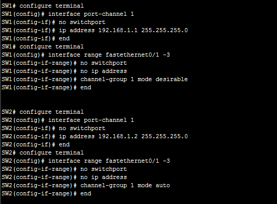
In this example, the FastEthernet 0/1-0/2-0/3 (on SW1 and SW2) must be aggregated; it is required to create a Layer3 etherchannel using PAgP with desirable mode on SW1 and auto mode on the SW2. The configuration is:
Switch-1 Configuration:
SW1# configure terminal
SW1(config)# interface port-channel 1
SW1(config-if)# no switchport
SW1(config-if)# ip address 192.168.1.1 255.255.255.0
SW1(config-if)# end
SW1# configure terminal
SW1(config)# interface range fastethernet0/1 -3
SW1(config-if-range)# no switchport
SW1(config-if-range)# no ip address
SW1(config-if-range)# channel-group 1 mode desirable
SW1(config-if-range)# end
[bodyads]
Switch-2 Configuration:
SW2# configure terminal
SW2(config)# interface port-channel 1
SW2(config-if)# no switchport
SW2(config-if)# ip address 192.168.1.2 255.255.255.0
SW2(config-if)# end
SW2# configure terminal
SW2(config)# interface range fastethernet0/1 -3
SW2(config-if-range)# no switchport
SW2(config-if-range)# no ip address
SW2(config-if-range)# channel-group 1 mode auto
SW2(config-if-range)# end

Note:
- The “no switchport” command is required to change interface from layer2 to layer3 mode.

